


 Рейтинг: 4.9/5.0 (1850 проголосовавших)
Категория: Windows: Расширения
Mobile Computer Control - «Mobile Computer Control» - MCC это система полноценного видео наблюдения (быстрый доступ к архиву, многопользовательский интерфейс, удаленный контроль, запись по расписанию и видеодетектору движения). Система удобна в управлении, проста для любого уровня пользователя ПК, подходит как для домашнего использования, но и для обеспечения безопасности на объектах малого и среднего бизнеса.
MCC позволяет производить наблюдение и управление всеми доступными Вам способами: с персонального компьютера, ноутбука, а также передавать видео изображение на мобильный телефон GSM. Благодаря MCC Вы не привязаны к своему компьютеру – «будьте мобильны».
Основные достоинства цифровой системы видео наблюдения MCC:
• Поддержка различных телекамер;
• Просмотр изображения в любой точке мира в режиме on-line через сотовый телефон или веб-браузер на компьютере;
• Управление компьютером и подключёнными устройствами через GSM телефон ;
• Поддержка веб-камер (USB), в том числе встроенных в ноутбук;
• Детектор движения, и автоматическое включение записи;
• Установка детектора движения только для части изображения (к примеру можно выбрать одну машину на стоянке)
• Запись по расписанию;
• Запись в формате avi, используя любой «кодек». (Рекомендуется DivX ;-) MPEG 4). Пользователь сам настраивает степень сжатия AVI файла.
• Возможность оповещения на сотовый телефон, включение Аудио записи и выполнение системной команды. на компьютере, по событию (к примеру событием может быть: продолжительное движение в зоне видимости камеры);
• Многопользовательский интерфейс доступа к информации через веб интерфейс (возможность запрета просмотра видео с отдельных камер пользователям);
• Простота установки;
• Лёгкость настройки;
• Поддержка до 50 камер (зависит от возможностей вашего ПК);
• Возможность присвоения имени видео камере;
• Выбор места для архива, в том числе и на сетевых дисках (сервере);
«Mobile Computer Control» не просто программа для наблюдения, но и ваш «доступ» к компьютеру и устройствам соединёнными с ним, с мобильного телефона, позволяющего Вам в любое время и в любом месте держать свой бизнес под полным контролем.
Находясь, к примеру, в кафе или делая покупки в супермаркете (если Вы, конечно, их там делаете) можно:
- просмотреть изображение с любой видеокамеры Вашей системы наблюдения;
- получить текстовое оповещение на «мобильный» (к примеру «движение в районе стола в поле видимости 3й камер»)
- запустить какой либо процесс на Вашем компьютере (архивирование данных, перезагрузка сервера);
- подключится к рабочему столу, и с помощью джойстика сотового телефона, управлять им;


Mobile Computer Control - программа для осуществления видеоконтроля. Mobile Computer Control может записывать получаемую с веб-камеры картинку на компьютер, передавать её на мобильный телефон, позволяет управлять компьютером через сотовый телефон. Есть встроенный планировщик записи и детектор движения (детектор движения можно настроить на конкретную часть принимаемой картинки). Поддерживаются USB-камеры. Изображение записывается в формат AVI, используемые при этом кодеки можно настраивать. При срабатывании датчика движения программа может не только включать видеозапись, но и отсылать сигнал на мобильный телефон или выполнять произвольную системную команду. Возможен доступ к камерам через веб-интерфейс, максимальное количество камер, с которыми может одновременно работать программа, ограничено пятьюдесятью. При помощи Mobile Computer Control вы можете превратить свой компьютер в полноценную систему безопасности и видеонаблюдения.
computer control — kompiuterinis valdymas statusas T sritis automatika atitikmenys: angl. computer control; computer based process control; computerized control vok. rechnergefuhrte Proze?regelung, f; rechnergefuhrte Regelung, f; rechnergefuhrte Steuerung, f rus.… … Automatikos terminu zodynas
computer control — supervision which is performed by a computer … English contemporary dictionary
Computer Control Company, Inc. — Computer Control Company, Inc. (1953–1966), informally known as 3C, was a pioneering minicomputer company known for its DDP series (Digital Data Processor) computers, notably the 1963 16 bit DDP 116 and the 24 bit DDP 24. It was founded in 1953… … Wikipedia
Computer Control Corporation — (1953 1966)(CCC или 3C), известна как производитель миникомпьютеров DDP (Digital Data Processor). Содержание 1 История 2 Продукция компании 3 Примечания … Википедия
Toyota Computer Control System — Das Toyota Computer Control System (TCCS) ist ein System zur Motorsteuerung des japanischen Autoherstellers Toyota, es wurde von dem japanischen Zulieferer Denso entwickelt. Der 4,3 Liter 3UZ FE Toyota Motor Von Aufbau und Funktion ist es… … Deutsch Wikipedia
distributed computer control system — paskirstytoji kompiuterinio valdymo sistema statusas T sritis automatika atitikmenys: angl. DCCS; distributed computer control system vok. verteilte Proze?rechnersystem, n rus. распределённая система компьютерного управления, f pranc. systeme de… … Automatikos terminu zodynas
Control engineering — Control systems play a critical role in space flight Control engineering or Control systems engineering is the engineering discipline that applies control theory to design systems with predictable behaviors. The practice uses sensors to measure… … Wikipedia
Computer Integrated Manufacturing — (CIM) is a method of manufacturing in which the entire production process is controlled by computer. Typically, it relies on closed loop control processes, based on real time input from sensors. It is also known as flexible design and… … Wikipedia
Computer network — Computer networks redirects here. For the periodical, see Computer Networks (journal). Datacom redirects here. For other uses, see Datacom (disambiguation). Internet map. The Internet is a global system of interconnected computer networks that… … Wikipedia
Computer networking — is the engineering discipline concerned with communication between computer systems or devices. Networking, routers, routing protocols, and networking over the public Internet have their specifications defined in documents called RFCs. [… … Wikipedia
Computer-integrated manufacturing — Manufacturing Systems Integration Program, NIST 2008. Computer integrated manufacturing (CIM) is the manufacturing approach of using computers to control the entire production process.[1] … Wikipedia
Computer-aided Model Railroading
Please be sure to see Do It Yourself for others interested in developing computer control systems. See the Manufacturers page for software that you can buy or get free to operate your model railroad.
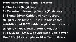
INFORMATION #15-1: For Information DCC Control of Turnouts, Go To the Section On Turnout Control.
INFORMATION#15-2: Manufacturers and Non-Programmers: An Argument For Ladder Logic.
Non-Programmers: Read this. If you like it, let your favorite manufacturer know!
Manufacturers: Consider this alternate method for programming your computer control systems.
I've programmed in just about every high level and assembly language there is. Like many programmers, I thought ladder logic was a joke. It's no joke. For some applications like controlling machines (read model trains), it's ideal! It's worth a serious look.
Most PLCs program using a graphical interface that shows relay contacts. This method of programming is even easier to learn than procedural language programming like C or BASIC. Many people who wouldn't dream of trying to learn to program a computer, do ladder logic and do it well. This is because that for the most part, ladder logic could really be implemented using relays. This is a visualization process that is easier to grasp than bytes, memory pointers and for-next loops. This makes it very popular.
Here is the above as it might be written in a computer language. With the exercise you just did, you should be able to make sense of this below.
If B_Occupied or T1_Thrown Then Red
If Not(B_Occupied) and C_Occupied and Not(T1_Thrown) Then Yellow
If Not(B_Occupied) and Not(C_Occupied) and Not(T1_Thrown) Then Green
Which approach agreed with you more? If you thought you understood it, but now you don't, don't feel bad. Now you appreciate ladder logic!
Below is an example of what you might see if the T1 turnout is thrown. In this simple example, T1 being thrown is all it takes to cause the red signal to light. It shows that blocks "B" and "C" are not occupied. Any input that is active is highlighted. Then the power is highlighted from left to right as far as it can go. Only the first rung makes it all the way across.
Troubleshooting is a breeze, too. I have been called to assist repair of machines that were totally unfamiliar to me. All I had to do was ask, what is the next thing this machine should be doing if it was working right? I'd search for the output that controlled that function. Inputs on the screen that were active would be highlighted. Just look at the rung from left to right, looking for inputs that weren't active, but should be. Then the sensor for that input was bad, needed adjusting, or a wire had broken or come loose. Total time to identify problem: under 15 minutes. In a model railroad, look for the block that has a train on it, but its input wasn't highlighted.
What makes ladder logic so successful as a troubleshooting tool is the graphical user interface.
So manufacturers, please give this some serious thought. I realize is a simple example. I'll be glad to discuss with you how ladder logic deals with timing, latching, comparing, counting, and more complex issues like math, dealing with data files and communicating on a network. I made those PLCs justify their cost every day!
A-B, I believe, now has their PLC-5 series being emulated on a PC. They are proud of their products and charge accordingly. I have a few good contacts at A-B and might be able to get to someone in A-B who might be in a position to licensing some bit of their technology at a reasonable price.
FAQ #15-3: Can I Use A PLC?
A programmable logic controller is an industrial control computer. It should not be confused with a PC — the personal computer you are using right now.
PLCs use something called ladder logic. When graphically displayed, it looks like rungs on a ladder. See above.
Many have logic elements that light up as a particular input is made. Allen-Bradley's progressively lit rungs make troubleshooting easy.
Until I actually worked with PLCs, I looked down at them as most programmers do. I was a hard sell. In the old days, they simply mimic'ed relay logic — which was the use of relays to control things. How smart could a cabinet full of relays be? Not very!
The modern PLC is sophisticated. It is ideally suited for controlling many things at once — like several model trains!
They typically have LEDs on their inputs and outputs. So looking at the front of the PLC, you can get a good idea what inputs the system is getting and what outputs it is controlling. In a factory, this is a big plus. Many technicians can troubleshoot a machine without hooking up a terminal to the PLC and looking at the program. If programming isn't your bag, this is very nice.
Of A-B, GE, and Siemens — the three biggest PLC manufacturers — A-B was by far the best. Easiest to use, reliable, system software that was bug free, operated just like the manuals said, and never crashed. Don't you wish your PC and its system software could be like this.
The systems that have lots of inputs and outputs are quite expensive. They do offer scaled down versions that are ideal for running things like candy machines. These units have limited expandability and typically have more inputs than outputs - since the typical machine needs more inputs than outputs.
Anyone thinking a PLC for model railroading is probably thinking signals. Here you need a lot of outputs compared to inputs. So these low cost models are not usually adequate for our needs.
Another thing to watch out for is that many inputs on these industrial machines are looking for 16-24V for an input signal — since 24V is what is typically used to run machine controls. Some DCC block sensors only put out about 5V. Typical PLC inputs would not detect this.
The way to look at PLCs is to see if you can do what you want to do for less than $14 per function. That's what a function, like a crossing signal, costs on a DS54. The DS54 can operate rail switches, crossing signals, and a few other things for the creative modeler. And you can network it, too!
While I feel that ladder logic is ideal for programming your DCC computer control system, the lack of low cost PLCs with lots of outputs makes them an uneconomical choice.
The one place a PLC may be the right thing is turntable control. You still have the problem of it not talking to your DCC network. Using DCC products on the market today, I haven't worked out how this might be done. In about a year, I will face that challenge. So stay tuned.
FAQ #15-4: DO I Need A Computer for DCC?
Absolutely, positively not! Unless you buy a super low cost DCC system that says "uses your computer to save you money," the answer is definitely no. The mainstream systems on the market today do not require a computer.
FAQ #15-5: Would A Computer Help Make DCC Easier to Use?
Except for loading speed tables, the answer is no. For one thing, the current DCC systems are not that hard to use. For another thing, a computer is hardly a walk around throttle! Lastly, setting up a computer to display your layout, indicate block detectors, and turnout positions is a good bit of tedious work. If you are brand new to DCC, trying to start out with a computer is a good bit of additional complexity you don't need. As I noted above, most DCC systems will work just fine without them.
Adding a computer later won't obsolete anything you buy now. So take two small steps — buy a DCC system, add a computer later — rather than a quantum leap to the computer.
IF YOU WANT TO GET SERIOUS ABOUT USING SPEED TABLES, then yes, a computer will make it much easier. Setting up speed tables without a computer is tedious. Fortunately, using a computer to set up speed tables doesn't require you to be a computer programmer.
Computer Control Software Suppliers
Please see the Manufacturers section for suppliers of DCC computer control software.
Vehicle Computer Diagnosis: Free to $100
(Prices good for most domestic or import cars and light trucks) Return to the Econofix Home Page
All vehicles from 1980 on (except for some big trucks) have some sort of computer engine controls. The fuel/air mixture and often the ignition timing are electronically adjusted by a computer according to engine load, speed, temperature, even the altitude above sea level!
The newer cars also use either the engine control computer (ECU, or Engine Control Unit) or a separate computer to shift the transmission. In the newest vehicles the throttle itself is controlled by the computer via an electric servo motor. There is no direct link to the throttle from the accelerator pedal. Control of systems like the throttle by a computer via servo motors is called "Drive By Wire". Modern vehicles use a computer, (or computers) and numerous computer sensors to control many aspects of a vehicle besides engine control. A bad computer sensor can cause many problems. A sensor error code can be misleading. Antilock Brakes and airbags are also controlled by their own separate computers. Computer problems can be hard to diagnose, but hopefully this will help.
The "Check Engine" or MIL light Computer Diagnostic Trouble Codes (DTC's) Intermittant computer sensor problemsSometimes a check engine light will go off after awhile: this means the computer sensor is reading "OK" again and the computer is happy. An intermittant sensor problem on most vehicles still causes a trouble code to be stored in the computer. The trouble codes can be erased from an older computer using a scan tool, or by disconnecting the battery or pulling the computer fuse for a few minutes. Some newer computer systems keep the codes until they are reset by a scan tool.
Limp Home ModeWhen the MIL (Check Engine Light) is on the computer will assume a set of values for the bogus values it's getting from the sensor. Your car may go into a "limp home mode" where the computer "assumed" sensor values make it run differently, even poorly, but it won't leave you on the side of the road. The car can get bad gas mileage and run poorly when in limp home mode, depending on which sensor is defective.
Reading Computer Trouble Codes Older VehiclesOlder vehicles had different ways of reading trouble codes from their computer. The computer interfaces were different, and the computer diagnostic capabilities varied widely. Some Japanese vehicles had LED lights that you viewed through a clear window in the side of the computer, which was under the seat. The computer blinked the codes to you. blink blink. blink. That's a code 21.
Some American vehicles would blink their MIL (Check Engine Light) to communicate computer codes: Chrysler/Mopar would blink codes to you if you turned the ignition switch on and off 3 times, leaving it on after the third time (This may still work!) GM would blink codes if you shorted between 2 terminals of the computer connector. A paper clip worked nicely.
Of course if you owned a shop you had a reader for each manufacturer's computer, or for the cars you worked on the most. Do it yourself-ers usually didn't have computer code readers because they cost hundreds of dollars. Also: the cars changed and computer software updates were required: manufacturers used the same computer trouble code number for different things on different years.
Newer Vehicle ComputerA newer vehicle computer (after 1996) has a standardized interface to access the computer trouble codes. Manufacturers agreed (under some government pressure) to develop a common interface to automotive computer functions. They called this interface "On Board Data", or "OBD". The latest version used is OBD 2 or "OBD II"
They even agreed on SOME terms: the computer that controls the engine is called the ECU, or Engine Control Unit, and the "Check Engine" light is called the MIL, or Malfunction Indicator Light.
Manufacturers can still have their own individual interfaces with the computer, but the OBD II computer (ECM) interface has to be there to sell a car in the USA.
Reading Trouble Codes with OBD IIYou need a scan tool to read OBD computer trouble codes, but they are fairly cheap ($40 or so basic, full featured $100-$150) and available at any parts store. The readers read out the computer trouble code number and give a brief description of the code's meaning, like "MAP sensor voltage low" and so on. The scan tool will also erase the codes from the computer and turn the MIL off.
Most computer sensor problems are diagnosed by checking resistance or voltage at the sensor or at the computer wiring harness connector. A digital multimeter is all you need for most sensor tests.
Computer Sensor ListManufacturers call their computer components by different names, but all the systems are similar in function. Here is a list of the most common sensors and what they do. Most all sensors povide a variable resistance to the computer to let it know what's happening. 5 volts are fed to the sensor, and it returns 0 to 5 volts back to the computer. Although later systems can do without certain sensors and still run, many systems will run poorly or not at all because of one defective sensor.
Show All Items
Want to toggle a power outlet between on or off with your computer? How about doing it with a remote? Sounds nice - I know. But the best is that you can make it all, and this will tell you how.
"Why would I want to turn a power outlet on or even OFF with my computer. "
Ever stub your toe getting out of bed to pee in the wee (tehe) hours of the morning? Enjoy mood lighting? Hell, maybe you just want to be a dweeb like me? This will make your life a little more easy, and if it doesn't do that it'll still make you super-swanky.
The great thing about this project is that it's not limited to a light - this is a computer controlled POWER OUTLET. So long as you're using a simple house-hold appliance this project is for you.
What makes this even cooler is that you can control 8 things with your parallel port (there are 8 data pins). So if turning a light on and off isn't enough for you then you can, potentially, turn your room into a TECHNO DANCE BAR!. or not.
You have to understand, before you try any of this, that I'm not responsible if you get injured; if any of your property is damaged, or if you get shocked - lighting your clothes on fire and turning you into a screaming human candle - I'm not responsible. So, please, be careful and pay close attention to any details. it'll save you a lot of annoyance and tribulation.
Mistakes only happen because of the unknown or overlooked. the closer you pay attention to what you're doing the less likely you'll be to make a stupid mistake. I know this because I am the master of stupid mistakes.
You're going to need a few things.
1. A computer control comprising
a housing,
a finger element extending above the housing and adapted to be gripped and moved by fingers in at least two dimensions to selected positions,
a pair of movable members mounted in the housing and coupled to the finger element for movement in respective orthogonal directions in response to corresponding movement of the finger element,
each of said pair of movable members including a light control grating defining alternating light and dark patterns along the corresponding direction of movement,
light emitting means and light responsive means disposed alongside each of the respective light control gratings for responding to light changes due to movement of each respective grating relative thereto wherein each light responsive means generates a pair of signals having opposite quadrature related phases for indicating motion in respective plus and minus directions of movement, and
means responsive to the pairs of signals for providing digital data corresponding to the two dimensional position of the control member.
2. A control as claimed in claim 1 wherein the pair of movable members includes respective upper and lower plates which are slidable in respective orthogonal directions along their planes and which have respective slots extending orthogonal to the respective directions of movement of the plates, the finger element includes a stem extending through the slots of the respective plates and the housing includes means retaining the plates such that the plates are only movable in their corresponding directions of movement, the stem being slidable within the slot of the corresponding member when the movement is in the orthogonal direction.
3. A control as claimed in claim 2 wherein the plates are elongated in respective dimensions perpendicular to the directions of movement of the respective plates, and the plate retaining means includes wall means of the housing for slidingly engaging opposite ends of the plates to retain the plate means.
4. A control as claimed in claim 3 where the plates have respective perpendicular extensions on the opposite ends thereof for preventing twisting and binding thereof when sliding along the respective wall means.
5. A control as claimed in claim 3 wherein the plates have respective head portions at one ends thereof such that the head portions define respective head walls extending perpendicular to the longitudinal dimension of the respective plates and along the directions of movement thereof, the grating means being formed in the respective head walls.
6. A control as claimed in claim 5 wherein the head portions also define respective head grooves extending on the sides of the head walls adjacent the plates; the gratings are formed by a pair of series of grating slots formed through the respective head walls wherein each grating slot extends perpendicular to the respective directions of movement and each series of grating slots extends along the direction of movement; the light emitting means includes respective pairs of light emitting diodes mounted in the housing and extending in the respective head grooves for directing light toward the head walls; the housing wall means includes a pair of housing wall recesses formed in the wall means alongside the respective head wall means; and the light responsive means includes respective masks secured in the respective housing wall recesses, each mask includes a pair of mask slots aligned with the series of grating slots in the respective head wall, each of the mask slots extending perpendicularly to the direction of movement of the respective head wall, pairs of semiconductor light sensing elements mounted in the respective housing wall recess for sensing light passing through the respective mask slots, and each pair of mask slots having a spacing therebetween selected to produce the respective pair of signals with quadrature related phases.
7. A control as claimed in claim 6 wherein the mask slots have a length which differs substantially from the lenth of grating slots with the shorter slots being centered relative to the longer slots so slight transverse movements of the head portions relative to their directions of movement do not cause modulation of light passing through the grating slots and the mask slots.
8. A control as claimed in claim 1, wherein the finger element is pivotally mounted in the top of the housing by a ball joint and has a stem extending downward in the housing; the pair of movable members are pivotally mounted in the housing for pivoting about respective orthogonal axes and each of the movable members includes an arcuate portion formed coaxial with the ball joint and including a slot in the arcuate portion co-planar with each respective member pivot axis for receiving the stem to couple the finger element to each movable member, and a sector portion with an apex on the respective member pivot axis and extending in a plane perpendicular to the member pivot axis wherein the respective grating is formed arcuately on each sector portion.
9. A control as claimed in claim 8 wherein the respective gratings are formed on arcuate flanges formed perpendicularly on the sectors.
10. A computer control as defined in claim 1 wherein the housing is adapted for being mounted underneath a cover of a keyboard, the finger element is adapted for extending upward through an opening in the cover of the keyboard, the finger element is movable within a plane extending parallel to the keyboard cover, and there is included a plate mounted over the housing for movement with the finger element and for extending relative to the opening in the computer keyboard cover for closing the opening.
11. A computer control as claimed in claim 1 including spring means for urging the finger element to a centered position relative to the movement in the two dimensions.
12. A computer control as claimed in claim 11 wherein the two dimensional movement of the finger element defines a rectangular area, and the spring means includes four springs extending diagonally in alignment with the four corners of the rectangular area so as to bias the finger element in a centered position.
13. a computer control as defined in claim 12 wherein the housing includes a top having a rectangular opening through which the finger element extends, there is included a collar on the finger element, and the four springs are tension springs mounted at one ends to the top at the respective corners of the rectangular opening and at the other ends to the collar.
14. A computer control as claimed in claim 1 wherein the upward extending finger element includes means extending into the housing for moving vertically relative thereto, means biasing the vertically movable means to an upward position, and means for detecting the downward vertical movement of the vertically movable means.
15. A computer control as claimed in claim 14 wherein the finger element includes a tubular member for movement in at least two dimensions, the vertically movable means includes a pin extending through the tubular member, the biasing means includes a spring biasing the pin upward, a vertically slidable cap secured over the upper end of the tubular member for engaging and moving the pin downward, a switch member mounted on the lower end of the pin member for movement therewith, and light sensing means for detecting the lower position of the switch member withn the housing for indicating depression of the cap.
16. A computer control as claimed in claim 1 including friction means for retarding movement of the finger element in one of the directions of movement thereof while permitting relatively free movement in another direction.
17. A computer control as claimed in claim 15 wherein the housing and the switch member include means for restricting movement of the switch member to movement in one of two orthogonal directions of movement of the finger element, the switch member includes a switch member slot for receiving the pin member and the pin member includes tab means for securing the pin member along the bottom side of the switch member at the switch member slot whereby the spring bias of the pin causes frictional engagement of the pin member tab means with the switch member to retard movement of the finger element along the switch member slot while the cap is not depressed.
18. A computer control as claimed in claim 17 including a second spring extending between the cap and the tubular member and biasing the cap upward whereby the spring force producing frictional resistance against movement of the finger element is less than the force required to depress the spring.
19. A computer control as claimed in claim 1 wherein the finger element includes means extending into the housing for rotating relative thereto, and there is included a means within the housing for determining the rotation thereof to provide an additional computer control signal.
20. A computer control as claimed in claim 19 wherein the rotating means includes a disc within the housing, disc grating means defining alternating dark and light areas on the disc means, and light responsive means for sensing movement of the disc grating means to generating a pair of quadrature related signals indicating movement of the disc grating means in response to rotation of the finger element.
21. A computer control as claimed in claim 19 wherein the rotating means includes a comb extending within the housing for being rotated to different positions, light means for generating light to pass through the comb and to be attenuated by the relative rotative positions of the comb, light detecting means, and analog to digital converting means for responding to the light detecting means to generate binary signals indicative of the rotative position of the control member.
22. A computer control as claimed in claim 1 wherein the gratings are formed by a pair of series of grating slots formed in the respective movable members wherein each series extends along central portions of one dimensions of the movable members leaving light blocking end portions at ends of the series of slots; the light responsive means includes a pair of masks mounted in the housing adjacent the respective gratings and having that light passing through the gratings and the mask openings modulated by movement of the gratings, and light sensing means mounted in the housing for receiving the modulated light to produce the pairs of signals with quadrature related phases; said masks and gratings are such that light passing through the gratings and the mask spring means and impinging on the light sensing means has at least a predetermined intensity but when said light blocking end portions are disposed over the mask opening means the light impinging on the light sensing means is reduced substantially below the predetermined intensity; and means responsive to the light sensing means for producing digital edge signals indicative of the finger element reaching an edge of travel.
23. A computer control comprising
a computer keyboard having a plurality of data entry keys in a planar arrangement defining a key plane,
a control device housing mounted in the keyboard below the key plane,
pattern means slidably mounted in the control device housing for movement in at least two orthogonal directions parallel to the key plane wherein the pattern means defines respective light control patterns extending in each of the two orthogonal directions,
a finger-grippable control element coupled to the pattern means and extending upward from the housing in the key plane for movement in two dimensions in the key plane to selectively move the pattern means to selected positions in its orthogonal directions of movement, and
light responsive means for responding to the light control patterns of the pattern means to generate signals indicative of the selected positions of the pattern, means in the respective orthogonal directions.
24. A computer control as claimed in claim 23 wherein the pattern means includes a pair of movable members mounted in the control device housing and coupled to the finger element for independent movement in respective orthogonal directions in response to corresponding movement of the finger element, each of said pair of movable members including a light control grating forming the respective light control patterns extending in each of the two orthogonal directions.
25. A computer control as claimed in claim 23 wherein the pattern means includes a carriage mounted in the control device housing for two dimension movement wherein the light control patterns are planarly disposed on the carriage.
26. A computer control as claimed in claim 25 wherein the light control patterns include respective grids.
27. A computer control as claimed in claim 25 wherein the light control patterns include a rectangular array of patterns wherein each pattern contains a plurality of regions with selected gray levels such that the combination of gray levels of the regions in each pattern are different from every other pattern.
28. A computer control as claimed in claim 23 wherein the computer keyboard includes a cover having an opening over the control device housing with the finger element extending upward through the opening, is finger element including a plate therein closing the opening in the cover.
29. A compurer control as claimed in claim 28 wherein the plate is slidable on the housing with the finger element being slidable therewith.
30. A computer cursor control as claimed in claim 23 including spring means for urging the finger element to a centered position relative to the movement in the two dimensions.
31. A computer control as claimed in claim 30 wherein the two dimensional movement of the finger element defines a rectangular area, and the spring means includes four springs extending diagonally in alignment with the four corners of the rectangular area so as to bias the finger element in a centered position.
32. A computer control as claimed in claim 23 wherein the finger element includes a tubular member for movement in at least two dimensions, the vertically movable means includes a pin extending through the tubular member, the biasing means includes a spring biasing the pin upward, a vertically slidable cap secured over the upper end of the tubular member for engagnng and moving the pin downward, a switch member mounted on the lower end of the pin member for movement therewith, and light sensing means for detecting the lower position of the switch member within the housing for indicating depression of the cap.
33. A computer control as claimed in claim 23 including friction means for retarding movement of the finger element in one of the directions of movement thereof while permitting relatively free movement in another direction.
34. A computer control as claimed in claim 1 wherein the finger element includes means extending into the housing for rotating relative thereto, and there is included a means within the housing for determining the rotation thereof to provide an additional computer control signal.
35. A computer control comprising
a stationary mask defining light transmissive opening means for passing light therethrough,
a movable member having a light control grating for moving across the mask opening means to modulate light passing through the grating and the mask opening means,
light emitting means and light detector means disposed upon respective opposite sides of the mask and grating such that the detector means generates an electrical detector signal which varies in accordance with light passing through the mask opening means and grating,
said mask and grating being such that light passing through the mask opening means and grating and impinging on the detector means has at least a predetermined intensity,
said movable member including an opaque end region at one end of the light control grating such that when the end region is over the mask opening the light intensity impinging on the detector means is reduced to less than the predetermined intensity to produce a corresponding change in the electrical signal from the detector,
means responsive to the detector signal for producing position changing control signals when the detector signal corresponds to light intensity above the predetermined intensity, and
means for producing edge control signals when the detector signal corresponds to light intensity below the predetermined intensity.
36. A computer control as claimed in claim 35 wherein the edge control signal producing means includes comparator means responsive to the detector signal being below a predetermined voltage for producing the edge control signal.
37. A computer control as claimed in claim 35 the means for producing position changing control signals includes means for producing a change signal indicative of changes in the detector signal, and hysteresis trigger means responsive to the change signal for producing a binary signal corresponding to movement of the grating; and the edge control signal means includes means for pulsing the light emitting means, and comparator means for detecting an absence of a change signal to produce the edge control signal.
38. A computer control comprising
a housing,
pattern means mounted in the control device housing for movement in at least two orthogonal directions wherein the pattern means defines respective light control patterns in each of the two orthogonal directions,
a finger-grippable control element coupled to the pattern means and extending upward from the housing for movement in two dimensions to selectively move the pattern means to selected positions in its orthogonal directions of movement,
light responsive means for responding to the light control patterns of the pattern means to generate signals indicative of the selected positions of the pattern means in the respective orthogonal directions, and
friction means associated with the finger element and pattern means for producing a retarding force to movement in one of the orthogonal directions substantially greater than a retarding force in the other direction.
39. A computer control as claimed in claim 38 wherein the signals for the light responsive means are adapted for use in controlling movement of a marker on vertical rectangular display of a computer monitor, and forward and backward movement in the one direction corresponds to up and down movement of the marker on the display.
40. A computer control comprising
grating means movable in at least one direction wherein the grating means defines alternating light and dark patterns extending across the direction of movement,
a stationary mask having a pair of spaced light transmissive slots disposed adjacent the grating means so that light passing through the slots is modulated by movement of the grating means,
a pair of light sensing elements aligned with the respective pair of slots for producing a pair of sensor signals corresponding to the intensity of light passing through the grating means and the respective slots,
said slots and grating means being such that the pair of sensor signals have opposite quadrature related phases corresponding to movement of the grating means in the respective opposite directions along the one direction of movement,
a pair of signal change means for generating respective change signals corresponding to changes in the sensor signals,
a pair of hysteresis trigger means for being operated by the respective change signals to produce square wave signals corresponding to the respective sensor signals, and
means responsive to the square wave signals for maintaining a count indicative of the position of the grating means.
41. A computer control as claimed in claim 40 wherein each of the pair of signal change means includes a differentiating circuit.
42. A computer control as claimed in claim 40 wherein each of the pair of signal change means includes an operational amplifier having one input connected to the output of the respective light sensing element, and integrating means connected from the output of the operational amplifier to the other input of the operational amplifier so that the output of the operational amplifier corresponds to changes in the sensor signals.
43. A computer control as claimed in claim 40 including end means at the opposite ends of the grating means for blocking light passage through a corresponding slot in the mask, a pair of means for generating corresponding edge signals in response to the corresponding sensor signals indicating the absence of light passage, means responsive to one of the edge signals for resetting the count to indicate a first edge position, and means responsive to the other edge signal for setting the count to indicate a second edge position.
44. A computer control as claimed in claim 43 wherein each of the pair of signal change means includes an operational amplifier having one input connected to the output of the respective light sensing element, nnd integration means connected from the output of the operational amplifier to the other input of the operational amplifier so that the output of the operational amplifier corresponds to changes in the sensor signals; and each of said resetting and setting means including comparator means connected to the output of the respective integration means for producing the respective edge signal.
45. A computer control as claimed in claim 43 includes light emitting means disposed on an opposite side of the grating means and the mask, and means for pulsing the light emitting means; and wherein said resetting and setting means are responsive to the respective signal change means indicating an absence of change signals during pulsing of the light emitting means for producing the respective edge signals.
46. A computer control comprising
grating means movable in at least one direction wherein the grating means defines alternating light and dark patterns extending across the direction of movement,
a stationary mask having a slot disposed adjacent the grating means so that light passing through the slot is modulated by movement of the grating means,
a light sensing element aligned with the slot and having a first resistance connected in series therewith to produce sensor signals corresponding to the intensity of light passing through the grating means and the slot,
said first resistance having a resistance value sufficiently high to produce a peak magnitude of sensor signal greater than a predetermined magnitude,
voltage responsive means for generating a pulse when a peak magnitude of the sensor signal exceeds the predetermined magnitude,
a counter for counting pulses from the voltage responsive means,
a plurality of resistance means controlled by outputs of the counter for selectively connecting adjustment resistances in parallel with the first resistance to reduce the magnitude of sensor signal to below the predetermined magnitude, and
means for converting the sensor signal to a binary signal useful in controlling a computer.
47. A computer control as claimed in claim 46 wherein the mask has a pair of spaced light transmitting slots disposed adjacent the grating means so that light passing through the slots is modulated by movement of the grating means; and there is included
a pair of light sensing elements aligned with the respective pair of slots and having a pair of respective first resistances connected in series therewith to produce a pair of sensor signals,
said slots and grating means being such that the pair of sensor signals have opposite quadrature related phases corresponding to movement of the grating means in respective opposite directions,
said first resistances having a resistance value sufficiently high to produce peak magnitudes of the sensor signals greater than a predetermined magnitude,
a pair of voltage responsive means for generating respective pulses when the respective peak magnitudes of the sensor signals exceed the predetermined magnitude,
a pair of counters for counting the pulses from the respective voltage responsive means,
a pair of plurality of resistance means controlled by outputs of the respective counters for selectively connecting adjustment resistances in parallel with the respective first resistances to reduce the magnitudes of the sensor signals to below the predetermined magnitude,
a pair of Schmitt triggers for converting the respective sensor signals to binary signals, and
means including counting means responsive to the binary signals for maintaining a count indicative of the position of the grating means.
48. A computer control as claimed in claim 47 including end means at the opposite ends of the grating means for blocking light passage through a corresponding slot in the mask, a pair of means for generating corresponding edge signals in response to the corresponding sensor signals indicating the absence of light passage, means responsive to one of the edge signals for resetting te count to indicate a first edge position, and means responsive to the other edge signal for setting the count to indicate a second edge position.
49. A computer control comprising
a pattern member having a plurality of light control patterns arranged in a two dimensional array wherein each pattern includes a plurality of regions each having a predetermined gray level selected from a pluralilty of different gray levels and wherein the combination of gray levels formed by the plurality of regions of each pattern differs from all the other patterns so as to define a code identifying the position of each pattern in the two dimensional array,
light means for illuminating the pattern member,
a rectangular array of light sensing elements for detecting the gray levels of the plurality of regions of at least one pattern on the pattern member,
finger-engageable means for moving either the pattern member, the array of light or light sensing elements relative to the other, and
means for determining the coding thereof to indicate the position of the pattern member relative to the array of light sensing elements.
50. A computer control as claimed in claim 49 wherein the pattern member includes a plurality of spots spaced interstitually between the patterns for indicating pattern positions.
51. A computer control as claimed in claim 40 wherein the count maintaining means includes means for indicating whether the last change in the count was up or down; means responsive to a change in state of a single one of the pair of square wave signals indicating movement of the grating in the same direction corresponding to the last change in count for correspondingly incrementing or decrementing the count; and means responsive to a change in state of both square wave signals for incrementing or decrementing the count, opposite to the indicated last change.
52. A computer control as claimed in claim 41 wherein each differential circuit includes a series connected capacitance for differentiating the sensor signals.
53. A computer control comprising
a stationary mask having light transmissive opening means for passing light therethrough;
a movable member having a light control grating extending near to but in spaced relationship to the stationary mask for moving across the mask opening to modulate light passing through the grating and the mask opening means;
a single light detector element disposed upon one side of the grating and the mask opening means;
a pair of light emitting diodes disposed upon the other side of the grating and the mask opening means wherein the light emitting diodes are spaced in a direction parallel to control grating;
means for alternately energizing the light emitting diodes at a rate which is at least twice a normal maximum rate of movement of grating cycles past the mask opening means;
means connected to the light detector element and operated in timed relationship with the alternately energizing means for generating a pair of detector signals corresponding to light intensity received by the light detector element during energization of the respective pair of light emitting diodes;
said mask opening means, said grating, said light detector element and said pair of light emitting diodes being spaced and arranged relative to each other so the pair of detector signals have quadrature related phases; and
means responsive to the pair of light detector signals for indicating a position of the grating relative to the mask to control a computer.
54. A computer control as claimed in claim 53 wherein the stationary mask is a molded plastic mask with a slot formed therein to form the mask opening means; and the movable member is a molded plastic member having a wall with the grating defined therein by a series of slots uniformly spaced along an axis parallel to a direction of movement of the member.
55. A computer control comprising
a finger grippable element movable in two dimensions in a two dimensional area of element movement,
computer means including a monitor having a two dimensional display on which a marker can be generated and moved within the two dimensions of the display,
means operated by movement of the finger grippable element for moving the marker on the display in correspondence with the movement of the finger grippable element in at least two different modes of movement including a first mode wherein the marker on the display is moved a large increment for each predetermined increment of movement of the finger grippable element, and a second mode wherein the marker on the display is moved a small increment which is substantially less than the large increment for each predetermined increment of movement of the finger grippable element, and
operator controlled switch means associated with the finger grippable element for operating the marker moving means selectively in the two different modes in correspondence with operation of the switch means.
56. A computer control as claimed in claim 55 wherein the second mode defines an area of marker movement on the display which in size is substantially less than the total area of the display.
57. A computer control as claimed in claim 56 including means for detecting when the finger element reaches an edge of movement thereof, and means responsive to the edge detecting means and switch means for shifting the area of marker movement in a direction corresponding to a detected edge of movement.
58. A computer control as claimed in claim 55 wherein the finger grippable element is movable within a two dimensional plane, and the marker moving means is operated by the two dimensional planar movement of the finger grippable element.
59. A computer control as claimed in claim 58 wherein the finger grippable element includes a depressable member for operating the switch means, and spring means for biasing the depressable member to a raised position on the finger grippable member.
60. A computer control as claimed in claim 58 wherein the finger grippable element includes plate means slidable in two dimensions in a horizontal plane, a tubular stem extending upward from plate means, a finger grippable cap mounted on the tubular stem for limited vertical sliding movement, spring means biasing the cap to a raised position, and pin means extending through the tubular stem for movement with the cap to operate the switch means.
61. A computer control comprising
grating means movable in at least one direction wherein the grating means defines alternating light and dark patterns extending across the direction of movement,
a stationary mask having a slot disposed adjacent the grating means so that light passing through the slot is modulated by movement of the grating means,
a light sensing element aligned with the slot and having variable resistance means connected in series therewith to produce sensor signals corresponding to the intensity of light passing through the grating means and the slot,
said variable resistance means having a high resistance value sufficiently high to produce a peak magnitude of sensor signal greater than a predetermined magnitude,
voltage responsive means for generating a pulse when a peak magnitude of the sensor signal exceeds the predetermined magnitude,
a counter for counting pulses from the voltage responsive means,
means controlled by outputs of the counter for selectively adjusting the resistance means to reduce the magnitude of sensor signal to below the predetermined magnitude, and
means for converting the sensor signal to a binary signal useful in controlling a computer.
62. A computer control having fine and coarse modes of marker positioning, comprising:
a finger grippable element movable in two dimensions in a two dimensional area of element movement;
computer means including a monitor having a two dimensional display area in which a marker can be generated and moved;
means operated by movement of the finger grippable element for moving the marker on the display in first and second modes of movement;
said marker moving means during the first mode of movement including means for moving the marker within a first area of marker movement about a current position of the marker in correspondence with movement of the finger grippable element within the area of element movement;
said first area of marker movement being only a portion of the two dimensional display area of the monitor;
said marker moving means during the second mode of movement including means for moving the marker within a second area of marker movement about a current position of the marker in correspondence with movement of the finger grippable element within the area of element movement; and
said second area of marker movement being larger than the first area of marker movement such that the first and second modes of movement define respective fine and coarse modes of marker positioning.
63. A computer control as claimed in claim 62 including means for detecting when the finger element reaches an edge of the two dimensional area of element movement, and means responsive to the edge detecting means during the first mode for shifting the first area of marker movement in a direction corresponding to the detected edge of the two dimensional area of element movement.
64. A computer control as claimed in claim 62 wherein the marker moving means includes a housing, plate means slidably mounted in the housing for movement in two dimensions, means operatively connecting the finger grippable element to the plate means for moving the plate means in correspondence with movement of the finger grippable element, and light detecting means for determining the position of the plate means to generate signals to control the position of the marker on the display.
65. A computer control as claimed in claim 64 wherein the plate means includes a pair of plates slidable in the housing in respective orthogonal directions, and light control grating means on each of the pair of plates for defining respective alternating light patterns in the corresponding directions to operate the light detecting means.
66. A computer cursor control comprising:
a housing;
plate means slidably mounted in the housing;
said housing including means for retaining the plate means in the housing and for permitting sliding movement of the plate means in two dimensions relative to the housing;
a finger grippable element operatively connected with the plate means and extending upward from the housing for enabling an operator to grip the element and to move the element within a two dimensional area of movement to move the plate means correspondingly in the two dimensions;
position determining means including light modifying pattern means mounted on the plate means, and light emitting and detecting means mounted on housing for sensing movement of the plate means in the two dimensions to determine the position of the finger grippable element in the two dimensional area;
computer means including a monitor with a cursor; and
means responsive to the position determining means for positioning the cursor on the monitor display at a position corresponding to the position of the finger grippable element.
67. A computer cursor control as claimed in claim 66 wherein said plate means includes a pair of movable members having respective upper and lower plates slidably mounted in the housing and coupled to the finger element for movement in respective orthogonal directions in response to corresponding movement of the finger element, and said light modifying pattern means including a light control grating on each of the pair of movable members for defining alternating light and dark patterns along the corresponding direction of movement to operate the light emitting and detecting means.
68. A computer cursor control as claimed in claim 67 wherein the upper and lower plates have respective slots extending orthogonal to the respective directions of movement of the plates; the finger element includes a stem extending through the slots of the respective plates; the retaining means of the housing includes means for retaining the plates such that the plates are only movable in their corresponding directions of movement, the stem being slidable within the slot of the corresponding member when the movement is in the orthogonal direction thereto.
69. A computer cursor as claimed in claim 68 wherein the plates are elongated in respective dimensions perpendicular to the directions of movement of the respective plates, and the plate retaining means includes wall means of the housing for slidingly engaging opposite ends of the plates to retain the plate means.
70. A computer cursor control as claimed in claim 69 where the plates have respective perpendicular extensions on the opposite ends thereof for preventing twisting and binding thereof when sliding along the respective wall means.
71. A computer cursor control as claimed in claim 69 wherein the plates have respective head portions at one end thereof such that the head portions define respective head walls extending perpendicular to the longitudinal dimension of the respective plates and along the directions of movement thereof, the light control gratings being formed in the respective head walls.
72. A computer cursor control as claimed in claim 71 wherein the head portions also define respective head grooves extending on the sides of the head walls adjacent the plates; the housing wall means includes wall recesses formed in the wall means alongside the respective head walls; and the light emitting and detecting means includes respective pairs of light emitting diodes mounted in the housing and extending in the respective head grooves for directing light toward the head walls, respective masks secured in the respective housing wall recesses, each mask including a pair of mask slots aligned with the grating means in the respective head wall, each of the mask slots extending perpendicularly to the direction of movement of the respective head wall, pairs of semiconductor light sensing elements mounted in the respective housing wall recess for sensing light passing through the respective mask slots, and each pair of mask slots having a spacing therebetween selected to produce a respective pair of signals with quadrature related phases.
73. A computer cursor control as claimed in claim 66 wherein the light modifying pattern means includes a plurality of light control patterns arranged in a two dimensional array with each pattern including a plurality of regions each having a predetermined gray level selected from a plurality of different gray levels and with the combination of gray levels formed by the plurality of regions of each pattern differing from all the other patterns so as to define a code which identifies the pattern and its position in the two dimensional array; and the light emitting and detecting means includes a rectangular array of light sensing elements for detecting the gray levels of the plurality of regions of at least one pattern, and means for determining the coding thereof to indicate the position of the plate means relative to the housing.
Description:
TECHNICAL FIELD
The present invention relates to computer control devices, and particularly to two-dimensional data entry devices which can be used for example to control the two dimensional positioning of a cursor or marker on a computer display or monitor.
DESCRIPTION OF THE PRIOR ART
One prior art technique for positioning the cursor on a computer monitor includes the use of four selected keys of a keyboard as positioning keys to move the cursor up, down, left and right, respectively. Many computer keyboards include special keys which have only the function of moving the cursor. In instances where the keyboard does not contain special cursor movement keys, a control key is provided for operating in the manner of a shift key to change the functions of selected keys normally used to enter letters, numbers, etc. to perform the cursor moving functions. Even though these cursor moving keys are often provided with automatic repeat functions, the cursor movement is relatively slow, and often requires multiple finger movements.
Various other devices have been used to provide for increased speed and control in movement of a cursor. Such devices include touch screens, light pens, tablets, mice, track balls, joysticks, and many other devices. Generally these devices suffer from one or more deficiencies such as requiring an operator to move his hand away from the keyboard, being relatively expensive, and/or requiring additional work or table space to operate.
SUMMARY OF THE INVENTION
The invention is summarized in a control for a computer, optionally mounted in the computer keyboard, wherein the control includes an upward projecting element which can be engaged and moved in two dimensions by fingers of one hand to correspondingly provide two dimensional data entry for the computer. The invention in particular features one or more provisions, such as the provision of a pair of members, coupled to the finger element for movement orthogonally within a housing and having respective light gratings which are utilized to operate digital circuitry providing data of the element position; the provision of movable members in the form of molded plastic plates having slots engaged by the finger element and with head portions molded with series of slots in walls thereof to form the gratings; the provision of the finger element being movable in a common key plane; the provision of a plate or skirt on the finger element covering a keyboard opening through which the finger element extends; the provision of a depressible cap which operates a vertical pin member sensed by a light sensor to indicate cap depression; a rotating disk coupled with the finger element and having a light grating producing rotative data in addition to the two dimensional data; the provision of circuitry which uses change in light detector signals to operate a binary or square wave signal producing circuit to eliminate calibration of the light detector circuit; the provision of opaque edges at the ends of gratings to produce detector signal levels indicative of the edges to accordingly reset and set counts corresponding to the position of the finger element; the provision of a retarding friction to motion corresponding to cursor up and down movement to reduce line jumping during horizontal movement; the provision of a circuit utilizing change in detector signals to operate hysteresis circuitry to produce a binary signal from light grating detector signals; the provision of automatic counter controlled parallel resistances to control light sensing element gain to eliminate circuit calibration; the provision of multiple gray level coding in plural regions of patterns spaced in two dimensions wherein decoding of the gray levels indicates position of the finger element; the provision of operator-controlled switch facilities associated with the finger element for selecting one of at least two modes of cursor movement such as fast and slow modes, or small and large increment modes of cursor movement; and/or the provision of a single light sensing element with a pair of alternately pulsed light emitters.
An object of the invention is to provide a substantially new and improved cursor control device for a computer which is less expensive and readily usable by operators.
An advantage of the invention is that a member is slidable within approximately a 1.25 inch (3.2 centimeter) square area corresponding to full movement of a cursor within a monitor with a resolution up to 2,048 by 2,048 or more points to control the positioning of the cursor.
Other objects, advantages and features of the invention will be aparent from the following description of the preferred embodiment taken in conjunction with the accompanying drawings.
BRIEF DESCRIPTION OF THE DRAWINGS
FIG. 1 is a perspective view of a broken-away portion of a computer keyboard illustrating a computer control device mounted upon a circuit board in accordance with the invention.
FIG. 2 is a perspective exploded view of the upper members of the computer control device of FIG. 1.
FIG. 3 is a perspective exploded view of the lower members of the computer control device of FIG. 1.
FIG. 4 is a cross-section view of the computer control device of FIG. 1.
FIG. 5 is a diagram illustrating the operation of moire pattern position detection and direction of the device of FIG. 1.
FIG. 6 is a diagram showing wave forms of respective detectors of the control device of FIG. 1.
FIG. 7 illustrates the use of one of the detectors for sensing a dark edge of the moire pattern.
FIG. 8 is a wave form diagram illustrating operation of the edge detection technique of FIG. 7.
FIG. 9 is an electrical diagram illustrating a basic moire grating detector circuit.
FIG. 10 is an electrical diagram of a modified moire grating detector circuit for use in the device of FIG. 1.
FIG. 11 is a waveform diagram illustrating respectively opposite-phased, binary, quadrature-related signals produced by moire grating movement in respective opposite directions.
FIG. 12 is a diagram of another modified moire grating detector circuit.
FIG. 13 is a schematic diagram of an electrical circuit utilizing the device of FIG. 1 for maintaining cursor position.
FIG. 14 is a flow diagram of a computer interrupt routine for controlling the position of a cursor in accordance with the device of FIG. 1.
FIG. 15 is an electrical circuit diagram of a modification to the circuit of FIG. 13 for indicating position of a control device.
FIG. 16 is an electrical diagram illustrating the employment of another modified detector and light source arrangement for detecting grating movement
FIG. 17 is an electrical diagram of edge detection circuitry suitable for use with the circuit of FIG. 15.
FIG. 18 is an electrical diagram of still another modification to the control circuit of FIG. 13.
FIG. 19 is an electrical diagram of a variation of interrupt circuitry for the control circuit.
FIG. 20 is an electrical diagram of still yet another modification for the control circuit.
FIG. 21 is a perspective view of a modified cover with a center return spring arrangement for substitution in the device of FIG. 1.
FIG. 22 is a broken-away cross-section view, in elevation, illustrating the employment of the center return arrangement of FIG. 21 in the device of FIG. 1.
FIG. 23 is a flow diagram of a modification to the routine of FIG. 14 for use with the modification of FIGS. 21 and 22.
FIG. 24 is a perspective view of a broken-away portion of a third axis or rotation sensor arrangement which may be included in the device of FIG. 1.
FIG. 25 is an electrical diagram of another further modification to the circuit for determining the positioning of the control device of FIG. 1 as modified by FIG. 24.
FIG. 26 is a top view with portions broken-away of variation of the control of FIG. 1 with 9 variations of the rotational or third axis sensor arrangement.
FIG. 27 is an elevational section of the device of FIG. 26.
FIG. 28 is an electrical schematic of a circuit for the third axis sensing arrangement of FIGS. 26 and 27.
FIG. 29 is a diagrammatic plan illustration of light paths and detection of the arrangement of FIGS. 26 and 27.
FIG. 30 is a top view with portions broken away of a variation of the control device for controlling the monitor cursor.
FIG. 31 is an elevational section view of the device of FIG. 30.
FIG. 32 is a grid pattern sheet utilized in the position indicating device of FIGS. 30 and 31.
FIG. 33 is a plan view of moire pattern and detector arrangement for sensing the movement of the pattern of FIG. 32.
FIG. 34 is a plan view of an modified grating pattern arrangement for being employed in the movement sensor of FIGS. 30 and 31.
FIG. 35 is a plan view of a moire pattern and detector arrangement for use with the grating patterns of FIG. 25.
FIG. 36 is a top view with portions broken-away of a variation of the computer control device wherein a rotational or joystick member is employed to control the cursor position.
FIG. 37 is an elevational section view of the device of FIG. 36.
FIG. 38 is an elevation view of a variation of the joystick type of digital control of FIGS. 36 and 37.
FIG. 39 is a side schematic view of a still further variation of the two dimensional control device of the present invention.
FIG. 40 is a plan view of a movable pattern arrangement employed in the device of FIG. 39.
FIG. 41 is a plan view of a detector array for use in sensing the positioning of the pattern sheet of FIG. 40.
FIG. 42 is an enlarged plan view of a portion of the pattern of FIG. 40.
FIG. 43 is an enlarged view of a portion of the detector of FIG. 41.
FIG. 44 is a flow diagram of another variation of a computer interrupt routine for controlling the position of a cursor.
FIG. 45 is an elevational front view of a computer monitor operating in accordance with one aspect of the invention.
DESCRIPTION OF THE PREFERRED EMBODIMENT
As illustrated in FIG. 1, a computer control device indicated generally at 50 in accordance with one embodiment of the invention is mounted upon a circuit board 52 by screws 54, or other fastening devices such as rivets, adhesive, etc. within a keyboard of a computer. The circuit board 52 may also support the keys 56 of the keyboard. The control device 50 includes a finger engageable member or element indicated generally at 60 which extends upward through an opening 62 in the keyboard cover 64 into the plane of the keys 56. The member 60 is designed to be easily gripped by the thumb, index finger, and middle finger in a manner similar to the gripping of a pencil. The member 60 and a plate or skirt 66 on which the member 60 is mounted are movable in two dimensions which are parallel or lie in the planes of the keys 56 and the plate 66 as indicated by the long and short dashed lines. In one variation of the device 50, the position of the member 60 within a square area, which is about 3.2 centimeters on each side, corresponds to movement of a cursor on a computer monitor. Moving of the finger engaging member 60 and plate 62 from one side to the other will result in corresponding movement of the cursor from one side of the monitor screen to the other side, and similarly movement of the finger member 60 from back to front (or up and down if oriented vertically) results in corresponding movement of the monitor cursor from top to bottom. Additionally, in a preferred embodiment, the finger member 60 may be depressed which results in a switch or key operation of the device 50 for use by the computer.
As shown in FIGS. 2, 3 and 4, the finger engageable member 60 includes a cap 70 which is suitably contoured on its outer surface for being engaged by the thumb and first two fingers of an operator's hand, and which is slidably mounted for vertical movement on a hollow stem 72 integral with the plate 66 and extending upward therefrom. Slots 74 are formed in opposite sides of the cap 70 to define inner resilient walls 76 which at the lower edges thereof have projections 78 extending inward for being received in recesses 80 formed in the outer surface of the stem 72. The recesses 80 have widths greater than the projections 78 so that the cap 70 can rotate through a small angle corresponding to the angle that fingers rotate due to pivoting of a hand at the wrist in side-to-side moving of the finger element 60. At the upper edges of the recesses 80 there are defined shoulders 82 which cooperate with the projections 78 to retain the cap 70 on the stem 72. A compression spring 84 is interposed between the upper annular ledge formed in the stem 72 and the interior upper surface of the cavity of the cap 70 for normally urging the cap 70 upward to engage the projections 78 with the shoulders 82.
A lower extension 90 of the tubular stem extends from the underside of the plate 66 downwardly into the device 50 and has a square cross-section which is slidably engaged in slots 92 and 94 formed in respective upper and lower slide members 96 and 98. The member 96 has a strip or rectangular plate body portion 100 in which the slot 92 is formed and a head portion 102 mounted on one end of the body portion 100. The slide member 98 similarly contains a strip or rectangular plate body portion 104 in which the slot 94 is formed, and a head portion 106 on one end of the body portion 104. The members 96 and 98 are contained within a cavity indicated generally at 110 in a housing 112. The distal edge 114 of the member 96 and a guide extension 115 thereon is slidingly supported upon a shoulder 116 of the housing 112, while the head portion 102 is slidingly supported upon a ledge 118 of the housing 112. The distal edge 114 and the outer wall of the head portion 102 define respective edges which are slidably retained between opposite walls 120 and 122 of the cavity 110 with a tolerance selected to restrict movement of the member 96 along an axis indicated by the double arrow headed line 124, while permitting relatively easy sliding movement of the member 96 within molding tolerances acceptable for mass production of the member. The extensions of the guide 115 and the head portion 102 tend to prevent twisting and binding of the plate 100. Similarly, the distal edge 126 of the member 98 with guide extension 127 is slidingly supported upon a shoulder 128 with the head portion 106 slidingly supported on the ledge 118 wherein the distal edge 126 is slidingly restrained by a vertical wall 130 extending upward from the ledge 128 and with the face of the head portion 106 slidingly engaging a vertical wall 132 for restraining sliding movement of the member 98 in a direction along the axis defined by double arrow headed line 134. The body portion 100 of the member 96, as well as its slot 92, are orthogonal to the body portion 104 and corresponding slot 94 of the member 98. The axes 124 and 134 are perpendicular to the respective slots 92 and 94 as well as to each other. When the finger engaging member 60 is moved, the square stem portion 90 slides within the slots 92 and 94 to move members 96 and 98 along the axes 124 and 134 to positions along the axes 124 and 134 corresponding to the two dimensional position of the member 60. The upper and lower members 96 and 98 are designed so that the plate body portion 100 slides on top of the plate body portion 104 and are retained within the housing 112 by a cover 140 which is secured to the outer upper edges of the housing 112 by adhesive, ultrasonic bonding, or other conventional technique.
In order to retain the plate 66 and the tubular stem 72 on the device 50, there is provided a pin member 144 extending through the central openings of the upper and lower stem portion 72 and 90. A compression spring 146 is contained between an upper collar 148 formed integral on the pin 144 and a annular inner shoulder 150 formed on the interior wall of the hollow stem portion 72 for urging the pin 144 upward. A lower end portion 152 of the pin 144 has a smaller diameter than the upper portion of the pin 144 and extends through a slot 154 in a guillotine member 156 which is also slidably contained within the cavity 110 of the housing 112 below the slide members 96 and 98. Tabs 158 extend outwardly from the reduced pin portion 152 for interlocking engagement with the upper surface of a recess 160 formed in the underside of the member 156 and extending along opposite sides of the slot 154 to retain the upper assembly of the skirt 66, stem 72, pin 144 and cap 70 on the device 50. A projection 159 of the pin 144 extends into an interior vertical slot 161 of the lower stem portion 90 to prevent the pin 144 from rotating relative to the stem and skirt. The guillotine member 156 is normally urged to a raised position by the spring 144 to engage the upper surface of the member 156 with small sliding projections 162 formed on the bottom edge of the square hollow stem portion 90.
The guillotine member 156 includes a strip or plate body portion 164 with wing portions 166 and 168 formed on respective opposite ends of the plate portion 164 perpendicular thereto for slidingly engaging respective walls 170 and 172 of the housing 112 to restrain movement of the guillotine member 156, when the finger member 160 is moved in its two dimensional directions, to movement along an axis indicated by double arrow headed line 174 which is parallel to the axis 134. For movement of the member 60 in a direction orthogonal to the axis 174, i.e. in the direction along axis 124, the lower pin portion 152 must slide in the slot 154 against the frictional forces produced by the tabs 158 and projections 162 engaging the respective lower and upper surfaces of the member 156. These frictional forces are determined by the spring factor of the spring 146 which is selected to produce a desired amount of resistance to sliding movement of the plate 66 and finger engaging member 60 along the axis 124. The axes 134 and 174 are preferably selected to correspond to left and right or X-direction of movement of the cursor while the axis 124 is preferably selected to correspond to upward and downward or Y-direction of movement of the cursor on the screen. The frictional resistance to movement of the two-dimensional cursor control in the up and down direction is found to improve the control device for certain applications such as word processing, vertical placement, etc. In word processing, the control device can be readily moved from left to right or from right to left while the functional resistance resists unwanted up or down cursor movement to adjacent lines. The frictional resistance can be released by depressing the cap 70 to depress the pin 144 slightly downward to release the gripping action of the tabs 158 and projections 152 on the member 156. The employment of the two springs 84 and 146 enables independent selection of the resistance to Y-direction movement and cap depressing force except that the cap depressing force must be equal to or greater than the spring force of spring 146; the depressing force can be made equal to the spring force 146 by illuminating the spring 84. During such depression the cursor control device 60 can be moved freely in its two dimensional field of movement.
As shown in FIGS. 3 and 4, the head 106 is elongated perpendicular to the body portion 104 and parallel to the axis 134 with central groove or slot 180 extending between opposite end walls of the head 106. The groove 180 thus defines a thin end wall 182 which slidingly engages the wall 132 and in which are formed a plurality of slots or openings 184 forming a grating therein. The slots 184 are uniformly spaced along the center portion of the length of the wall 182 with the longitudinal dimension of each slot 184 extending vertically and with the width dimension of each slot extending horizontally. The slots 184 have a width which is substantially equal to the spacing or opaque bars between the slots 184. A pair of light-emitting diodes 190 and 192 are contained within a recess 194 formed in the ledge 118 of the housing 112 and extend upwardly therefrom into the cavity 180 such that the LEDs 190 and 192 direct light toward the slots 184. A light blocking shield 196 extends upward from the ledge 118 to block light from one of the LEDs 190 and 192 crossing in front of the other. Projections 198 from the cover 140 engage the LEDs to insure proper positioning.
A stationary mask member 202 is contained within a recess 204 in the base housing 112 opening through the wall 132. The mask 202 has a thin wall section 206 extending parallel to the wall 182. The wall 206 contains two slots 208 and two slots 210 which are aligned with the row of slots 184 for selectively passing light to respective light sensors such as photodiodes or phototransistors 212 and 214 which are contained within the mask member 202 and held by cover projections 215. The slots 208 are elongated in the vertical dimension and have a width and spacing equal to the width and spacing of the slots 184, and the slots 210 similarly have an elongated vertical dimension and a width and spacing equal to the slots 184. However, as shown in FIG. 5, the spacing of the slots 208 from the slots 210 is selected so that the slots 208 are 90° out of phase (quadrature phase related) with the slots 210, i.e. if the spacing from the beginning of one opening 184 to the beginning of the next opening 184 as shown by the double arrow line 216 is considered as one cycle, than the openings 208 are offset relative to the openings 210 by one-fourth of the cycle as illustrated by the distance 218.
The size and number of openings 184, 208 and 210 are selected to produce a desired excitation of the sensors 212 and 214 under fully open conditions and to produce a desired resolution in detecting movement of the openings 184 relative to the openings 208 and 210. The width of the openings 184, 208 and 210, typically 0.02 inches (0.5 millimeters), is selected to produce the desired resolution or number of openings 184 limited in smallness by the minimum width which is practical for production of parts by high volume plastic molding techniques. In one example there are 31 openings 184 producing a resolution of about 84 points. The number of the openings 208 and the number of the openings 210 can be one, two (as illustrated in FIG. 5), or more, and is selected to provide sufficient light passage to produce adequate modulation of the conductivity of the photosensing elements 212 and 214. In one embodiment employing typical phototransistors 212 and 214, it is found that one opening 208, such as illustrated in FIG. 7, provides about 60 to 80% of the maximum excitation of the phototransistor by light passing through a plurality of the openings 208.
It has been discovered that improved operation is obtained by making the length of the openings 184, i.e. the height or longitudinal dimension of the openings 184, substantially greater or smaller than the length of the openings 208 and 210 and centering the length of the shorter opening relative to the longer opening. In order to permit relatively easy movement of the slide member 96, it must be manufactured with sufficient tolerance relative to the height of the recess in the housing containing the slide member. During movement of the slide member 96, some vertical movement of the member 96 relative to the stationary portions is unavoidable. Such relative vertical movement results in unwanted modulation of light passing through the openings 184 and 208 and 210. The different length and centering of the openings 184 relative to the length of the openings 208 and 210 avoids such unwanted modulation of light. As illustrated in FIG. 4, typically the openings 184 can be made with a dimension of about 0.085 inch (2.2 millimeters) and the openings 208 and 210 can be made with a length of about 0.075 inch (1.9 millimeters).
Referring back to FIG. 3, the head portion 102 is substantially similar to the head portion 106 in that it contains a wall 224 extending parallel to the direction 124 and having a plurality of slots 226 formed therein substantially similar to the wall 182 and slots 184 of the head 106. The wall 224 is spaced from a wall 228 to define a longitudinal groove or slot therebetween into which extend upper portions of light-emitting diodes 230 and 232 which have their lower portions mounted in a recess 234 in the ledge 118 similar to LEDs 190 and 192. A mask 236 is contained within a recess 238 in the wall 122 and has a wall 240 containing respective pairs of openings 242 and 244 substantilly identical to the mask 202. Phototransistors 246 and 248 have upper light sensing portions aligned with the respective pairs of openings 242 and 244 and have lower portions retained within the housing 112 similar to the retention of the phototransistors 212 and 214.
Additionally, there is contained an LED 252 retained within a cavity 254 in one side wall of the housing 112 and a phototransistor 256 retained in a recess 258 in the opposite wall of the housing 112. The housing is provided with openings (only opening 260 shown in FIG. 3) which extend from the respective recesses 254 and 258 toward each other so that light from the LED 252 normally impinges upon the phototransistor 256. These openings 260 are disposed below the normally raised position of the guillotine member 156 such that when the cap 70 of the finger member is depressed to lower the pin 144 and the guillotine member 156, light from the LED 252 is interrupted by the lowered guillotine to reduce the conductivity of the phototransistor 256 to produce a switch indication.
The LEDs 190, 192, 230, 232 and 252 and the phototransistors 212, 214 246, 248 and 256 are connected to circuitry on the printed circuitboard 52, FIG. 1, in a conventional manner. As shown for the LEDs 190 and 192 in FIG. 5, the LEDs will be energized by current through respective resistances 270 and 272. Movement of the slide member 98 and its corresponding wall 182 causes modulation of the light passing from the LEDs 190 and 192 through openings 184 and respective openings 208 and 210 to modulate the conductivity of the photosensors 212 and 214 as shown by the wave forms 274 and 276 in FIG. 6. It is noted that these wave forms 274 and 276 are phase shifted relative to each other by about 90° per cycle 216 of movement of the wall 182.
Photodiodes can be substituted for the phototransistors utilized in the control 50. Such substitution is illustrated by photodiodes shown in dashed lines 274 and 276 in FIG. 5. The photodiodes produce substantially similar conductivity curves as those shown in FIG. 6. The phototransistors have the advantage of producing a higher degree of change in conductivity relative to change in impinging light since the base emitter current is amplified in the collector emitter current of the phototransistor. Photodiodes have the advantage of being faster in response. Thus, phototransistors are preferred in applications where relatively high gain or output is desired, and photodiodes are preferred where the circuit must respond rapidly to changes in light intensity such as in sampling or rapid pulsing applications.
The current flow through or voltage across the light sensors is converted into binary signals suitable for use by digital logic circuit and/or computer circuitry. One type of converting circuit is illustrated in FIG. 9 for the light sensor 212. The light sensor 212 is connected between the emitter of a transistor 280 and a -V voltage source. The base of the transistor 280 is grounded and the collector of the transistor 280 is connected in series with a resistance 282 to the +V source. A Schmidt trigger inverter circuit 284 produces a square wave output in response to movement of the grating 182 past the openings 210, as illustrated by the wave form AX in FIG. 11. A similar circuit (not shown) including the light sensor 214 will produce a signal BX. It is noted that the phase of AX relative to BX when the grating 182 is moved in the +X direction is different than the phase of AX relative to BX when the grating is moved in the -X direction as illustrated by the respective upper and lower pairs of wave forms AX and BX in FIG. 11. These wave forms represent binary signals which are illustrated in Table 1 which can be sensed by logic circuitry or computer circuitry to determine movement and the direction of movement of the grating 182.